Cluster Creation and Configuration
Scope
This chapter covers the architectural decisions, tooling, and governance model for Kubernetes cluster creation, configuration, and lifecycle management. It addresses: distribution selection and node OS configuration; cluster provisioning tooling (Helmfile, Sidero Omni, Crossplane) and the two-layer profile delivery model; CNI selection and network policy enforcement; traffic routing, Gateway API, and on-premises load balancing; DNS and certificate management (cert-manager, ExternalDNS); storage tiers and the role of CSI; cluster profiles as the governance and configuration baseline; bringing existing clusters under Portainer management; cluster upgrade strategy and lifecycle governance; and the disaster recovery topology used by this reference architecture.
Cluster Architecture Principles
The cluster creation and configuration model rests on principles that govern how clusters are provisioned, configured, and maintained across the fleet.
Portainer governs from Day-2; it does not provision clusters. Cluster provisioning is the responsibility of dedicated tooling (Helmfile, Sidero Omni, Crossplane). Portainer takes ownership once the cluster’s API server is reachable. The separation between provisioning and governance tooling is deliberate — Portainer must never become a dependency for cluster creation.
Cluster profiles are the governance baseline. Every cluster must be built from a version-controlled cluster profile. Ad-hoc cluster configuration is not permitted. The profile encodes distribution, CNI, storage classes, gateways, admission control, certificate management, and observability agents — all applied at provisioning time.
Configuration is delivered in two independent layers. The OS layer (Talosconfig, kernel arguments, extensions) is managed by provisioning tooling. The Kubernetes component layer (CNI, CSI, admission controllers, observability agents) is managed by Helmfile. Both are version-controlled and applied at cluster creation; neither modifies the other’s concerns.
Immutability is preferred over patching. Talos OS is the reference choice because it eliminates node-level SSH access, prevents ad-hoc configuration, and makes node state reproducible and auditable. Where enterprise Linux is used, golden images serve the same goal.
Network policy enforcement is not optional. The namespace-as-tenancy model depends on CNI-enforced NetworkPolicies. A CNI that does not enforce NetworkPolicy makes the multi-tenant isolation model inoperable.
cert-manager and ExternalDNS are mandatory baseline components. No cluster enters production without automated TLS certificate lifecycle management. These are operational prerequisites for any cluster that exposes services externally.
3.1 Cluster Lifecycle Model
A cluster’s lifecycle spans four phases. Day-0 and Day-1 are owned by third-party provisioning tooling; Portainer's governance begins at Day-2.
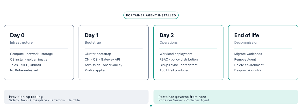
Day-0 — Infrastructure Provisioning (outside Portainer's scope)
Infrastructure is established entirely by provisioning tooling — Sidero Omni, Crossplane, Terraform, or a cloud provider CLI. No Kubernetes distribution exists at this stage.
- Compute: physical nodes, VMs, or cloud instances
- Networking: VLANs, subnets, IP address management, firewall rules
- Storage: SANs, NAS, or cloud block storage
- OS installation: general-purpose Linux image or Talos OS applied via the Talos API
Portainer has a basic integration with Sidero Omni for Talos bare-metal provisioning, but Day-0 infrastructure largely remains outside Portainer's scope.
Day-1 — Cluster Bootstrap and Baseline Configuration (Portainer joins at end of phase)
The Kubernetes distribution is bootstrapped and the cluster profile (section 3.6) is applied by the provisioning tooling chain:
- Control plane initialised; worker nodes joined
- CNI, CSI driver and StorageClasses, Gateway API controller deployed
- Admission control (Gatekeeper or Kyverno) installed with base constraint library
- Observability agents installed; baseline RBAC and namespace structure applied
- Final step: Portainer agent installed — the cluster becomes a managed environment
Portainer has some integration into popular cluster lifecycle management tools, so platform teams can provision clusters from within Portainer’s user interface.
Day-2 — Ongoing Operations (Portainer's primary domain)
This is where Portainer governs. All ongoing configuration, workload management, and compliance evidence is produced here:
- Workloads deployed and updated through Portainer's stack management
- RBAC assignments managed centrally; policy updates distributed from the Portainer control plane
- Cluster component changes (distribution upgrades, CNI/CSI updates) tracked as profile version increments and rolled out in a controlled sequence
- Portainer's audit trail provides the primary compliance evidence for all Day-2 configuration changes
- Monitoring, alerting, and log collection governed by Chapters 9–12
Decommissioning
- Migrate workloads to a target cluster before decommissioning; Portainer's environment visibility supports migration planning
- Remove the Portainer agent; delete the environment from Portainer — this removes RBAC assignments, GitOps stack definitions, and audit references without affecting the cluster itself
- De-provision infrastructure through the same tooling used at Day-0
Design for multi-cluster from day one. A single cluster is a valid starting point, but growth, workload isolation requirements, and compliance boundaries consistently drive organisations toward multi-cluster architectures over time. Retrofitting consistent CIDR allocation, profile governance, and identity models across an already-sprawling fleet is significantly more expensive than designing for it upfront. The CIDR decisions (section 3.3), cluster profile framework (section 3.6), and identity model (Chapter 4) made for the first cluster establish the patterns that must scale to the tenth and hundredth. Treat the first cluster as the pilot of a fleet, not a self-contained deployment.
Multi-cluster architecture patterns. How clusters relate to each other follows recognisable patterns, each with distinct trade-offs. The cluster-centric model is the correct default for enterprise governance deployments: it maps directly to Portainer’s environment group model, makes compliance boundaries explicit, and keeps access control predictable at scale. The profile framework in section 3.6 is designed around it.
Cluster-centric — the model used throughout this reference architecture — treats clusters as the primary organisational unit with defined purposes: production, staging, regulated, edge. Workloads are deployed into purpose-defined environments; governance, profiles, and access controls are cluster-scoped. This maximises predictability and makes compliance boundaries explicit, at the cost of workload flexibility.
Application-centric architectures treat clusters as interchangeable execution environments; applications drive placement rather than cluster purpose. This suits globally distributed deployments with strong automation, but requires consistent configuration across all clusters to prevent fragmentation.
Replicated architectures run identical clusters across regions or availability zones for resilience and latency — appropriate where consistent user experience or failover is a first-class requirement, but every configuration change must be applied fleet-wide.
Split-by-service architectures separate clusters by workload type (frontend, backend, data processing, regulated) optimising each for its profile, at the cost of more complex cross-cluster networking.
3.2 Distribution and Node Configuration
Distribution selection and node OS selection are closely coupled decisions — the distribution determines what Kubernetes runs, and the node OS determines the environment it runs on. Both are encoded in the cluster profile (section 3.6) and applied at cluster creation time.
3.2.1 Node Operating System
The choice of node operating system directly affects reliability, manageability, and security posture. Two OS families are approved within the reference architecture. All OS images must be produced as golden images, versioned, and maintained centrally.
| OS Class | Description | Typical Use |
|---|---|---|
| Enterprise Linux | Traditional Linux distributions with established governance, patching frameworks, operational tooling, and enterprise support models (RHEL, Ubuntu, SLES). | Datacentre and cloud clusters requiring alignment with existing enterprise practices and tooling ecosystems. |
| Kubernetes-Specific OS | Immutable, image-based OS designed solely to run Kubernetes. Removes configuration drift and enables deterministic node behaviour. Examples: Talos OS, Flatcar, Bottlerocket. | Edge and remote clusters where consistency, reduced attack surface, and low-maintenance node lifecycle are critical. Production clusters where host immutability is a security requirement. |
Secure boot, disk encryption, and API-driven configuration are the three properties that most significantly differentiate Kubernetes-specific immutable operating systems from traditional enterprise Linux. Talos OS provides all three by design: nodes boot only signed images (secure boot), all data at rest is encrypted, and the entire node configuration lifecycle — from initial provisioning through upgrades and decommissioning — is driven by the Talos API with no SSH access surface. This makes Talos nodes deterministic, auditable, and resistant to configuration drift at the OS level. Where Talos is adopted, these properties are non-negotiable; they are the primary architectural reason for the choice.
Node sizing depends on the cluster role and workload profile. Control plane nodes require sufficient resources to run etcd, the API server, scheduler, and controller manager reliably under load — a minimum of 4 vCPU, 8 GB RAM and SSD disk for production control planes is typical, with more for clusters with high API request rates or large object counts. Worker nodes are sized against observed workload resource demands; production sizing should not be extrapolated from theoretical maximums alone. For edge and constrained nodes (KubeSolo, K3s), minimum viable sizing is workload-specific: small edge devices may operate with 2 vCPU and 2 GB RAM, while industrial edge nodes may require significantly more depending on local compute requirements. Node sizing is defined in the cluster profile (section 3.6) for each cluster type and must not be left to per-node ad-hoc decisions.
Nodes are disposable execution units. Whether running Talos or an enterprise Linux distribution, nodes must never become special or irreplaceable — workloads must not depend on specific node identity, local state, or configuration that exists only on one host. This principle drives the immutable OS preference, the golden image requirement, and the centralised sizing definition in cluster profiles: when any node can be replaced with an identical copy, maintenance and node loss become routine rather than disruptive.
3.2.2 Kubernetes Distribution Selection
Portainer supports all CNCF-conformant Kubernetes distributions, broadly split into these categories:
| Distribution Type | Description | Typical Use | Examples |
|---|---|---|---|
| Immutable Kubernetes | Secure, immutable, purpose-built minimal operating system. | ||
| Upstream-aligned, predictable behaviour, no platform lock-in, consistent across all environments. | Preferred default for all new deployments. | Vanilla Kubernetes, Sidero Talos | |
| Edge-optimized Kubernetes | Small, resource-efficient. Purpose-built for edge environments. | Single-node or small-cluster edge deployments | KubeSolo, K3s |
| Cloud Managed Kubernetes | Control-plane management is offloaded to the cloud provider while still supporting the governance patterns in this document. Platform lock-in inevitable. | Cloud-first environments. | EKS, AKS, GKE. |
| Vendor-Augmented Kubernetes Platforms | Enterprise distributions layered on top of upstream Kubernetes. These are often not slimmed down — additional binaries increase the attack surface and additional services require explicit security review. | Existing enterprise investment only. Must be explicitly managed; not recommended as the default for security-sensitive deployments. | OpenShift, Rancher, Tanzu |
The distribution choice shifts operational responsibility, not the underlying architecture. The Kubernetes control plane model is consistent across all distributions — what changes is who owns availability, upgrades, and recovery for each component. With on-premises self-managed distributions (Talos, vanilla Kubernetes), the platform team owns the full stack: control plane HA, etcd backup, node lifecycle, and upgrade sequencing. With cloud-managed distributions (AKS, EKS, GKE), the cloud provider manages control plane availability and version upgrades; the platform team retains responsibility for node pools, add-on components, and networking. With vendor-augmented platforms (OpenShift, Tanzu), control is shared but abstracted, often reducing flexibility while increasing support dependence. Understanding where responsibility sits determines what operational capability the platform team must build — choosing a distribution the team cannot sustainably operate at the required security posture is an architectural failure regardless of technical merit.
Managed Kubernetes reduces operational labour by approximately 15–30% compared to fully self-managed deployments [1]. The control plane is managed, but GitOps pipelines, identity and access, policy enforcement, and observability still require full internal engineering effort. Teams that adopt managed Kubernetes expecting to eliminate platform engineering effort are consistently disappointed — the responsibility shift is real but partial.
Within the upstream-aligned category, two options deserve specific architectural attention. Talos OS is the recommended default choice for new environments — fully API-driven, immutable, with no SSH access and a minimal attack surface — and is covered in detail in section 3.2.1. When combined with upstream Kubernetes, it provides the most security-hardened node baseline of any option in this category.
KubeSolo serves two distinct use cases that share a common architectural requirement: single-node Kubernetes without clustering overhead.
At the industrial edge , devices are deployed as independent units because clustering is impractical. Factory floors, retail point-of-sale, remote field sites, and industrial IoT gateways run workloads on isolated hardware where each node must function independently with small, predictable failure domains.
In enterprise data centres , many organisations operate Docker fleets numbering in the hundreds or thousands of standalone servers. These servers run independently by design — high availability lives at the application layer, not the infrastructure layer. The architecture is intentional and critical to their operational model.
Both use cases face the same false choice: remain on Docker and lose access to the modern Kubernetes ecosystem, or adopt Kubernetes and inherit the complexity of a system designed for multiple nodes. KubeSolo removes that false choice. It delivers the full Kubernetes API on a single node — Helm, CRDs, Operators, Namespaces, RBAC, admission controls, and declarative deployments — while removing everything that only exists to serve a cluster: no scheduler (there is only one node), no quorum, no cluster networking overlay, no distributed control plane lifecycle to manage. A Docker host can become a KubeSolo host with minimal disruption; the operational model and application-layer HA strategy remain intact.
KubeSolo provides the Kubernetes API surface that modern software vendors now mandate, on infrastructure that neither needs nor wants a cluster. It is managed centrally by Portainer through the Edge Agent with no distinction in the management model from any other environment. Edge deployment patterns are covered in Chapter 2, section 2.3.
Selection guidance: KubeSolo targets sub-1GB RAM environments, specifically sub-512MB — the tightest constrained hardware — with a runtime footprint of approximately 200MB RAM. For devices with 1GB or more RAM, K3s, K0s, or MicroK8s are more appropriate; those distributions are CNCF-certified and widely supported. KubeSolo is not currently CNCF-certified — the optimisations required to achieve its low memory footprint do not fully meet CNCF’s certification criteria. For enterprises with CNCF certification obligations in regulated environments, this must be explicitly accepted before adoption.
Distribution selection is guided by four criteria: compliance requirements (FIPS, CIS benchmarks, vendor support obligations), operational model (cloud-managed vs. self-managed, upgrade frequency tolerance), connectivity profile (always-connected data centre vs. intermittent edge), and team capability (existing expertise and operational tooling ecosystems). An architecturally superior distribution that the operations team cannot sustainably maintain at the required security posture is a poor choice in practice.
3.2.3 Control Plane High Availability
Control plane HA topology — the number of control plane nodes, etcd quorum configuration, and API server load balancer placement — must be defined before cluster provisioning begins. These decisions are immutable: changing them post-creation requires a full cluster rebuild.
📋
Control plane HA topology is outside the scope of this reference architecture. The correct configuration depends on your availability requirements, failure domain design, and infrastructure constraints. The decisions below must be made explicitly and encoded in the cluster profile (section 3.6) before cluster creation.
Control plane node count: Three control plane nodes is the minimum for production HA — one etcd node failure tolerated. Five nodes tolerate two simultaneous failures and are appropriate for critical infrastructure or regulated environments with stricter availability SLAs. Single-node control planes are not acceptable for production clusters.
etcd topology: Stacked etcd — etcd co-located on control plane nodes — is the default for Talos and most distributions in the reference architecture and is appropriate for the majority of deployments. External etcd — a dedicated etcd cluster separate from the Kubernetes API server — provides stronger failure domain isolation at the cost of significant operational complexity. Use external etcd only where the etcd failure domain must be provably independent of the API server failure domain.
API server load balancer / virtual IP: Production clusters require a stable, load-balanced API server endpoint so that control plane node rotation does not break cluster or agent connectivity. For on-premises and bare-metal Talos clusters, Kube-VIP running on control plane nodes is the standard choice. The endpoint address must be defined before the first control plane node is bootstrapped — it is encoded in the Talosconfig and cannot be changed post-creation. Encode the HA topology decision in the cluster profile (section 3.6) and in the Sidero Omni machine class definition or Talosconfig template (section 3.7).
SLA and staffing implications: Each increase in uptime commitment — from 99% to 99.9% to 99.99% — increases the labour required to operate and maintain the platform by 20–30% per additional nine [1]. More redundant nodes require more upgrade coordination, more HA testing, and deeper incident response capability to sustain. HA topology decisions are therefore not purely technical — they carry direct staffing and operational cost implications that must be planned before committing to a specific availability SLA, not discovered after.
3.3 Networking and CNI Selection
The CNI is a foundational cluster component — it determines network policy capability, observability depth, and performance for all workloads. The reference architecture validates two CNI options for production use:
Cilium is the recommended CNI for new deployments. Its eBPF-based data plane provides native network policy enforcement, deep flow-level observability, and significant performance advantages over iptables-based alternatives. Cilium also serves as the implementation layer for Gateway API (section 3.4) via its built-in Gateway API controller, making it the natural choice for clusters adopting the full reference stack. Requires Linux kernel 5.10 or later (5.15+ recommended). CNI version compatibility with the chosen Kubernetes distribution must be validated and tracked as part of the cluster profile (section 3.6).
Calico is the validated alternative for environments where Cilium's kernel requirements cannot be met, or where operational familiarity favours Calico. Calico provides mature, well-tested network policy enforcement and broad distribution and cloud-provider support.
Flannel and Canal are not recommended for new deployments. Flannel does not support Kubernetes NetworkPolicy natively — this disqualifies it from the namespace isolation model described in Chapter 4. Canal adds Calico policy on top of Flannel but introduces unnecessary complexity with little benefit over Calico directly.
Network policy enforcement is a hard requirement for the namespace isolation and tenancy model (see Chapter 4). CNI selection must support Kubernetes NetworkPolicy at minimum; Cilium's extended policy model is preferred for regulated environments.
CIDR and subnet planning is a cluster-creation-time decision that cannot be changed post-provisioning without rebuilding the cluster. Pod CIDR, Service CIDR, and node subnet allocation must be defined before the CNI is deployed; this is outside the scope of this reference architecture and depends on your network topology, fleet size, and multi-cluster connectivity requirements.
📋
Two constraints apply regardless of the ranges chosen. Pod CIDRs and Service CIDRs must be unique and non-overlapping across all clusters in the fleet — this is mandatory in any deployment using Cilium Cluster Mesh or cross-cluster service routing; assign a unique pod CIDR block to each cluster at fleet planning time, not per-cluster at creation time. Size the pod CIDR to accommodate the maximum expected pod count with headroom — validate that the CNI’s per-node allocation block (by default /24 in Cilium) does not exhaust the cluster CIDR before the cluster reaches its node ceiling. Service CIDR must not overlap with pod CIDRs, node subnets, or any routable external network segment. CIDR decisions must be documented in the cluster profile (section 3.6) for each cluster type.
Cluster-to-cluster networking for multi-cluster fleets is a separate concern from CNI selection; evaluate Cilium Cluster Mesh or a service mesh overlay (Istio, Linkerd) for east-west cross-cluster traffic.
3.4 Traffic Routing and Gateway API
Gateway API is the reference model for all new cluster deployments. It is the strategic successor to the Kubernetes Ingress API — now generally available — providing a role-oriented model (GatewayClass, Gateway, HTTPRoute, TLSRoute) that cleanly separates infrastructure concerns (cluster operator) from routing concerns (application team). This separation maps directly to Portainer's RBAC model and the namespace-as-tenancy construct covered in Chapter 4.
The reference implementation uses Envoy-class controllers : Envoy Gateway (recommended for Cilium-based deployments), Cilium Gateway API (prefer Envoy Gateway), Contour, or Emissary Ingress (formerly Ambassador). All are Envoy-based and implement the Gateway API spec; choice is primarily driven by existing operational familiarity or ecosystem investment. All must integrate with cert-manager for automated TLS certificate lifecycle, define a GatewayClass per cluster, and be included in the cluster profile (section 3.6).
North–south load balancing by environment type:
| Type | Usage |
|---|---|
| Cloud | Native cloud provider load balancers (ALB, Azure Load Balancer, GCP LB). |
| Datacentre | MetalLB or Kube-VIP, selected and defined by the cluster profile. |
| Gateway | Gateway API controllers with Envoy-class implementations. Must integrate with cert-manager and define a GatewayClass per cluster. |
On-Premises Load Balancing: MetalLB and Kube-VIP
Cloud-managed clusters receive load balancers automatically when a Service of type LoadBalancer is created — the cloud provider provisions the external endpoint. On-premises and bare-metal clusters have no equivalent integration; without additional tooling, LoadBalancer services remain permanently in Pending state. MetalLB and Kube-VIP fill this gap.
MetalLB is a Kubernetes-native load balancer implementation for bare-metal environments. It operates in one of two modes.
L2 mode uses ARP (IPv4) or NDP (IPv6) to announce service IPs from a configured address pool. One node at a time owns each assigned IP and receives all traffic for it. L2 mode requires no BGP-capable network infrastructure and works in any flat network — it is the simpler choice for environments without routing infrastructure. The trade-off is that traffic is not distributed across nodes at the load balancer layer; failover is ARP-based and can take 10–30 seconds when the owning node becomes unavailable.
BGP mode establishes a BGP session with upstream routers and announces service IPs as routes. Traffic is distributed across all cluster nodes via ECMP at the network layer, providing genuine load distribution and fast failover. BGP mode requires a BGP-capable router that accepts peering from the cluster, but is the correct choice for production environments where traffic distribution and failover speed matter.
In Cilium environments, MetalLB can be replaced entirely. Cilium includes a native LoadBalancer IPAM capability and a BGP control plane (via GoBGP) that announces service IPs without deploying a separate component. When Cilium is the CNI — the reference choice in this architecture — using Cilium’s built-in LB IPAM and BGP announcements is the preferred path. It reduces cluster component count and eliminates the dependency management surface between MetalLB and Cilium.
Kube-VIP serves two distinct functions that are often conflated. Its primary role in this reference architecture is API server HA — it runs as a static Pod on control plane nodes and uses leader election to assign a virtual IP to one control plane node at a time, providing a stable API server endpoint without an external hardware load balancer (see section 3.2.3). Kube-VIP also supports LoadBalancer service assignment in the same L2 and BGP modes as MetalLB. In environments already running Kube-VIP for API server HA, enabling its service load balancing capability avoids deploying a second component.
Choosing between them for service load balancing:
- If Cilium is the CNI: use Cilium’s native LB IPAM — no additional component required
- If Kube-VIP is already deployed for API server HA: extend it to cover service load balancing
- Otherwise: MetalLB is the standard choice, with broader ecosystem familiarity and tooling support
Regardless of choice, the IP address pool must be pre-allocated from the network team and defined in the cluster profile before any LoadBalancer services are deployed. Pool ranges must not overlap with any other subnet in the environment.
Legacy ingress controllers (NGINX, Traefik, HAProxy): Acceptable for existing environments only — not the recommended path for new deployments. Where retained, they must be version-pinned within the cluster profile and treated as a technical debt item with a documented migration timeline to Gateway API.
Portainer Server exposure: whether via Gateway API or a legacy controller, the Portainer Server endpoint must terminate TLS, restrict access to internal networks or VPN, and integrate with cert-manager — see Chapter 2, section 2.7.
Service mesh (Istio, Linkerd) as an east–west complement to Gateway API north–south routing: evaluate when cross-namespace or cross-cluster mTLS is required at the application layer.
3.5 DNS and Certificate Management
DNS and TLS certificate management are not optional add-ons to the networking stack — they are required for any cluster that exposes services outside the pod network. Gateway API controllers and ingress controllers both depend on cert-manager for TLS termination; ExternalDNS makes those services resolvable. The three are operationally coupled: a Gateway or HTTPRoute annotation triggers cert-manager to issue a certificate and ExternalDNS to publish a DNS record, and only when both succeed does traffic reach the cluster.
Sound DNS and certificate management are required for every environment, needed for any inter-service communication, such as Portainer and a self-hosted IdP (Keycloak, Authentik).
cert-manager
cert-manager (CNCF Incubating) automates the full TLS certificate lifecycle: issuance, renewal, and revocation. It integrates natively with Gateway API and legacy ingress controllers via annotations or CRD-based Certificate resources, and stores issued certificates as Kubernetes Secrets consumed by the ingress or gateway for TLS termination. cert-manager is a mandatory baseline component in the cluster profile (section 3.6) — no cluster enters production without it.
Issuer types: cert-manager supports multiple certificate sources via its Issuer and ClusterIssuer CRDs.
- ACME (Let’s Encrypt / ZeroSSL): Automated public CA certificates using HTTP-01 or DNS-01 challenge solvers. HTTP-01 requires the cluster to be reachable from the public internet. DNS-01 works with internal or non-public clusters and is required for wildcard certificates — supported via provider plugins for Route53, Azure DNS, Cloudflare, and others. Use DNS-01 for all production certificates; HTTP-01 is acceptable only for public non-production environments.
- Internal CA (Vault PKI / OpenBao PKI): For air-gapped or regulated environments where public CA certificates are inappropriate, cert-manager integrates with Vault or OpenBao’s PKI secrets engine to issue certificates from an internal CA. This is the reference pattern for internal cluster communication, mutual TLS between services, and regulated environments with certificate authority requirements. The issuer authenticates to Vault using the Kubernetes auth method (Chapter 8).
- Self-signed and CA bootstrapping: ClusterIssuers of type selfSigned are used to bootstrap a cluster-local CA that other issuers then reference. Appropriate for development clusters or as the root for an internal CA chain; not for production workload certificates.
Integration with Gateway API: Annotate Gateway or HTTPRoute resources with cert-manager.io/cluster-issuer to trigger automatic certificate issuance. cert-manager watches for annotated resources, requests a certificate from the configured issuer, stores it as a Secret, and renews it automatically before expiry. Certificate readiness can be monitored via the Certificate CRD status and should be included in cluster health checks.
Air-gapped environments: Public ACME issuers are unavailable. Use Vault or OpenBao PKI (Chapter 8) as the internal issuer, or provision certificates out-of-band and import them as Kubernetes Secrets. The Vault PKI engine can run air-gapped; cert-manager communicates with it over the internal network without external connectivity.
ExternalDNS
ExternalDNS (CNCF Incubating) automates DNS record management by watching Kubernetes Gateway, Ingress, and Service resources and creating or updating records in the configured external DNS provider. When a Gateway resource is created with a hostname, ExternalDNS publishes an A or CNAME record pointing to the load balancer IP or hostname, making the service resolvable without manual DNS intervention. It is the operational complement to cert-manager: cert-manager handles the certificate; ExternalDNS handles the DNS record.
Supported providers: AWS Route53, Azure DNS, Google Cloud DNS, Cloudflare, NS1, and many others via provider plugins. Configure ExternalDNS with the minimum IAM permissions required to manage records in the target DNS zone only — not across the entire DNS account.
Ownership model: ExternalDNS uses a TXT record-based ownership mechanism to track which records it manages. This prevents ExternalDNS from modifying records created manually or by other systems, and enables safe deletion when a Kubernetes resource is removed. Configure --txt-owner-id to a unique value per cluster to avoid ownership conflicts in multi-cluster environments sharing the same DNS zone.
Source types: Configure ExternalDNS to watch Gateway , HTTPRoute , Ingress , or Service (type LoadBalancer) resources as sources. In Gateway API deployments, watching Gateway and HTTPRoute provides the most complete coverage.
Air-gapped and split-horizon DNS: For air-gapped clusters, ExternalDNS is not applicable — DNS records are managed manually or via internal DNS servers not reachable from the public internet. For split-horizon DNS environments (where internal and external resolvers return different records for the same hostname), deploy separate ExternalDNS instances targeting the internal and external DNS zones respectively, scoped by annotation or namespace selector.
Service exposure workflow
The full service exposure workflow, once cert-manager and ExternalDNS are deployed:
- Platform engineer creates a Gateway or HTTPRoute resource with a hostname and TLS configuration
- cert-manager detects the annotation, requests a certificate from the configured issuer, stores it as a Secret
- ExternalDNS detects the resource, creates a DNS record pointing to the load balancer
- The gateway controller picks up the Secret and terminates TLS
- Traffic reaches the cluster at the configured hostname over HTTPS
All three components — cert-manager, ExternalDNS, and the Gateway API controller — must be included in the cluster profile (section 3.7) and deployed as part of the Day-1 baseline. Deploying them after workloads are running creates a remediation burden; deploying them at Day-1 makes TLS and DNS automatic for every service from the first deployment.
CoreDNS
CoreDNS is the default in-cluster DNS resolver installed automatically by most Kubernetes distributions and requires no additional deployment effort. Its configuration , however, warrants explicit attention in environments that integrate with enterprise DNS infrastructure. The CoreDNS ConfigMap in the kube-system namespace defines upstream forwarders, stub zones, and rewrite rules — settings that differ meaningfully between cluster types. Enterprise environments typically require: a forwarder pointing to the organisation’s internal DNS resolvers rather than public resolvers, for private domain resolution; stub zone definitions for internal domains not handled upstream; and response timeout tuning aligned with the organisation’s DNS infrastructure. The CoreDNS ConfigMap belongs in the cluster profile and must be version-controlled and applied via the Helmfile Day-1 baseline — not configured ad-hoc after cluster creation.
3.6 Storage and CSI
Storage varies across environments but must follow consistent patterns. StorageClasses must be standardised and performance characteristics clearly documented. The reference architecture defines three storage tiers:
| Storage Type | Usage |
|---|---|
| Block Storage | Cloud block (EBS, Azure Disk), SAN CSI, NVMe CSI for primary workloads. Must support snapshots and dynamic expansion. |
| Shared File Storage | NFS/SMB CSI for workloads requiring POSIX semantics. Not suitable for databases or stateful transactional workloads due to consistency and performance characteristics. |
| Local Storage | Local-path CSI for edge and single-node clusters (KubeSolo, K3s). Provides reduced resiliency and is not suitable for HA workloads. |
For the Portainer Server's own persistent storage, block storage is mandatory: bboltDB requires low-latency random-write performance that network-attached or shared file storage cannot reliably provide. NFS-backed PersistentVolumeClaims must not be used for the Portainer database volume — this constraint is covered in detail in Chapter 2, section 2.5.
Storage class design should follow a consistent naming convention across the fleet, enabling cluster profiles and GitOps workload definitions to reference storage tiers by name without being tied to a specific provider. The reference naming convention is: fast-ssd for low-latency SSD-backed block storage, standard-hdd for standard block storage, shared-nfs for shared POSIX file access, and local-path for edge and single-node environments. The default StorageClass for each cluster type is defined in the cluster profile (section 3.6); workloads that do not specify a storage class receive this default.
CSI driver selection follows the environment type: cloud-native CSI drivers (EBS CSI, Azure Disk CSI, GCP PD CSI) for cloud-hosted clusters — native provider support removes operational overhead and provides snapshot and dynamic expansion capability.
Portworx, Linbit or rook-ceph for on-premises clusters requiring distributed block storage without the operational complexity — lightweight, Kubernetes-native, and appropriate for on-premises fleets.
In air-gapped and edge environments , storage options are constrained by physical hardware and the absence of cloud provider integrations. Local-path CSI is the practical default for single-node edge deployments. For multi-node edge clusters, both Portworx, rook-ceph and LINBIT SDS operate entirely within the cluster boundary without external dependencies. LINBIT SDS’s support for ARM and other processor architectures is specifically relevant for constrained industrial or OT edge hardware; Portworx’s operator-based deployment integrates cleanly with the cluster profile model. Select based on whichever is already in use elsewhere in the fleet — avoid splitting operational expertise across two distributed storage platforms. Network storage (NFS) at the edge should only be used if backed by a locally-sited, reliable NFS server; cloud storage backends are not available in air-gapped environments.
3.7 Cluster Profiles
Ad-hoc cluster configuration — where each cluster is configured independently, by hand, at onboarding time — produces configuration drift, compliance gaps, and inconsistent security postures across the fleet. Cluster profiles address this through standardised, version-controlled configuration templates that encode the approved baseline for each cluster type.
💡
Portainer does not define, store, or apply cluster profiles — they are an architectural pattern implemented entirely in the provisioning tooling layer (Sidero Omni, Crossplane, or Helmfile), which operates beneath Portainer’s governance scope.
A cluster profile defines: the approved Kubernetes distribution and version range, the CNI plugin and configuration, the Gateway API or ingress controller and TLS policy, the CSI storage solution and its storage classes, the admission control policy components (Gatekeeper) with the base constraint library, the monitoring agent configuration, the baseline RBAC and namespace structure, and the Kubernetes API server audit logging configuration. The cluster profile baseline must also include default-deny network policies, ResourceQuota, and LimitRange for all tenant namespaces — ensuring namespace isolation controls are applied consistently at cluster creation. The full namespace isolation and tenancy model, including Portainer's RBAC integration and the optional Capsule extension, is covered in Chapter 4.
The cluster profile must also specify Kubernetes API server audit logging configuration — the audit policy, log format, and sink target. Audit logging must be enabled on all production clusters; it is an API server parameter configured at cluster creation time and cannot be activated retroactively without restarting the API server (on Talos, via a machine config update through Sidero Omni). The required sink for all production clusters is the fleet SIEM — see Chapter 10.
Profiles are maintained by the platform team, versioned in Git, and applied consistently at cluster creation time.
- Profile types by use case: production cluster, staging cluster, edge cluster, regulated cluster (with stricter baseline)
- Profile components are applied at cluster creation time by the provisioning tooling chain — usually via Helmfile for specific layers of the stack (CNI, CSI, ingress, admission control, observability agents).
- Drift detection: identifying clusters that have diverged from their assigned profile over time
- Profile versioning and update rollout strategy: how profile changes propagate to existing clusters in a controlled sequence
- Relationship to prerequisites: cluster profiles assume the foundational controls (identity, registry, security baselines) are in place before a cluster is built to the profile
Cluster profiles also define node scheduling policy. GPU and specialised hardware nodes require explicit labelling and tainting to ensure workloads land only on nodes that meet their hardware requirements, and that general-purpose workloads do not inadvertently consume accelerator resources. GPU nodes should be labelled (e.g., nvidia.com/gpu: "true" ) and tainted (e.g., nvidia.com/gpu=present:NoSchedule ); only workloads that explicitly tolerate the taint are scheduled onto these nodes. Admission control (Chapter 7) enforces that workloads declare appropriate tolerations and node selectors.
Node labelling and tainting strategy more broadly should be defined centrally in the cluster profile and applied consistently at node provisioning time. Labels encoding the node's role ( node-role.kubernetes.io/worker ), environment tier ( environment: production ), and hardware class ( storage-class: nvme ) allow scheduling policies and pod affinity rules to reference stable, meaningful attributes rather than ephemeral or provider-specific identifiers. Labels applied inconsistently — or not at all — produce unpredictable scheduling behaviour that is difficult to diagnose and impossible to govern systematically.
The reference architecture defines three base profile types, each encoding the full Infrastructure Plane standard for that environment class:
| Profile | Characteristics |
|---|---|
| Production | Strict declarative mode, enforcing admission control, full observability agents, HA storage, immutable OS preferred, no direct API access. |
| Non-production | Relaxed ClickOps permissions, audit mode admission control acceptable, standard storage, faster lifecycle iteration. |
| Edge / Far-edge | Single-node (KubeSolo), local-path storage, async Edge Agent, minimal resource footprint, resilience to connectivity loss and power interruption. |
Clusters must not diverge from their assigned profile. Deviations must be tracked as exceptions, reviewed, and remediated. Profile drift is a compliance and operational risk. All components defined in the cluster profile must carry explicit version pins — floating tags ( latest or unversioned references) are not permitted in any profile definition. Version drift between the profile definition and the applied cluster state is a compliance gap.
Profile implementation — the tooling used to apply and maintain profiles, including how they are delivered to clusters at Day-1 and kept up to date — is covered in section 3.7.
3.8 Cluster Provisioning, Profile Delivery, and Lifecycle Tooling
Cluster creation is out of scope for Portainer — Portainer manages clusters that already exist. However, the tooling used to provision and maintain clusters has direct implications for the operational model described in this chapter. Cluster profiles exist as configuration artefacts in a Git repository, applied to a cluster by provisioning tooling during Day-1 bootstrap; Portainer takes over governance only after the cluster is provisioned, configured, and the agent installed. Three approaches are relevant to the reference architecture: Helmfile for profile delivery across all cluster types, Sidero Omni for Talos-based bare-metal clusters, and Crossplane for infrastructure-as-code provisioning across cloud and hybrid environments.

Helmfile (Profile Delivery)
The reference implementation uses Helmfile as the profile orchestration layer. A helmfile.yaml declares all Helm releases that constitute the profile baseline — CNI plugin, CSI driver and StorageClass definitions, ingress or Gateway API controller, cert-manager, admission control (Gatekeeper or Kyverno with the base constraint library), and observability agents. Environment-specific configuration is expressed as values files ( values-production.yaml , values-edge.yaml , etc.) rather than separate Helmfiles, so the release list is shared and only the parameterisation differs between profile types. Helmfile is executed by a bootstrap pipeline or script immediately after the Kubernetes API server is available, before the Portainer agent is installed.
Sidero Omni (Talos Cluster Management)
Sidero Omni is the cluster lifecycle management platform for Talos OS clusters. It provides centralised, API-driven cluster lifecycle management — bootstrapping, upgrading, scaling, and decommissioning Talos clusters from a single control point. For organisations adopting Talos OS as the strategic node OS (section 3.2.1), Omni provides the provisioning layer that Talos itself does not include.
Within the cluster profile architecture, Omni manages the node OS configuration layer — Talosconfig, Talos extensions, and kernel arguments — independently of the Kubernetes component layer above it. Both layers are required for a complete Talos cluster profile: Omni handles the OS baseline before any Kubernetes component is deployed; Helmfile (or Crossplane Compositions) handles the Kubernetes component baseline above it. The two layers are independent and neither substitutes for the other.
Talos image selection and the Image Factory: Talos OS images are generated by the Talos Image Factory — a build process that compiles a specific set of kernel extensions and system services into an immutable image. Unlike traditional Linux distributions, Talos has no package manager and no shell; extensions cannot be installed post-boot. Every driver, kernel module, or system service a cluster node will need — storage initiators, GPU drivers, additional NIC support, hardware security tooling — must be selected before the first node boots and compiled into the image at factory time. Extension selection is therefore a cluster profile decision, not a node-level configuration.
Different profile types typically require different extension sets. Common examples: DRBD kernel module for Piraeus-Datastore/LINSTOR or Longhorn distributed storage; iSCSI initiator for Longhorn, Portworx or OpenEBS iSCSI-backed volumes; Nvidia GPU drivers and the Nvidia container runtime for GPU-enabled node pools; vendor-specific NIC drivers (Mellanox, Broadcom) for hardware requiring out-of-tree modules; TPM2 tooling where hardware-based node attestation is required. The Image Factory produces a versioned image URL that encodes the Talos version and the full extension set as a single immutable unit. This URL must be version-controlled in the cluster profile and referenced in the Sidero Omni machine class definition. Profile types that require different extension sets each need a separate image reference.
When upgrading Talos OS, a new image must be generated from the Image Factory for the target version carrying the same extension set. The updated image URL is pinned in the machine class definition and rolled out via Omni’s rolling upgrade mechanism (see Cluster Upgrade Strategy above). Extension changes and OS version changes are always co-ordinated at the image level — there is no mechanism for post-boot extension management on a running Talos node.
Current enterprise integration limitations: The Sidero Omni integration does not currently satisfy advanced enterprise cluster profile requirements. The following capabilities are on the roadmap as of this writing (May, 2026)
- Multi-NIC configuration: Enterprise nodes commonly have multiple network interfaces serving distinct functions (management, storage, workload, BMC). Omni's current machine configuration model does not fully support per-interface differentiation in a profile-driven way.
- Disk and partition configuration: Production cluster profiles require deterministic disk layout — OS on a specific device, data on another, etcd on a dedicated partition. Omni does not currently support the level of disk partitioning specificity required by regulated environments. Manual configuration patches can be applied to satisfy these requirements.
- Profile-based repetitive deployment: Deploying clusters from a reusable, version-controlled profile — where every cluster of a given type is guaranteed identical — requires profile templating that goes beyond Omni's current machine class model.
Until these capabilities are available, Sidero Omni should be evaluated for non-production Talos deployments and edge clusters where profile complexity is lower. It remains on the roadmap as the target provisioning path for production Talos clusters once the above gaps are addressed.
Crossplane (Infrastructure-as-Code Provisioning)
Crossplane provides a Kubernetes-native approach to infrastructure provisioning: clusters, networks, databases, and other infrastructure resources are declared as Kubernetes custom resources and reconciled by Crossplane controllers. For organisations already operating Kubernetes as the platform of record, Crossplane offers a consistent provisioning model across cloud providers and on-premises infrastructure. Cluster creation becomes a GitOps operation — a pull request against a cluster manifest triggers Crossplane to provision the infrastructure and bootstrap the cluster.
- When to prefer Crossplane: multi-cloud or hybrid environments where infrastructure provisioning must be standardised across providers; organisations with strong GitOps adoption who want provisioning and workload deployment to share the same tooling model; platform teams with high Kubernetes API fluency.
- Profile delivery with Crossplane: where Crossplane is the provisioning layer, cluster profile components can be encoded as a Crossplane Composition , making cluster creation and profile application a single declarative operation. This is the preferred model for Crossplane-based environments — it replaces the separate Helmfile bootstrap step with a unified provisioning declaration.
- Crossplane vs. Sidero Omni: these are not mutually exclusive. Crossplane addresses cloud and IaaS provisioning; Sidero Omni addresses Talos OS bare-metal. A mature fleet may use both.
- Integration with Portainer: Once a cluster is provisioned by either tool, it is onboarded to Portainer through the standard agent installation workflow. Provisioning tooling and management tooling operate as independent layers.
Cluster Upgrade Strategy
Cluster upgrades follow the same two-layer model as initial profile delivery. For Talos clusters, upgrades are sequenced: OS layer first via Sidero Omni, Kubernetes distribution second via the Talos upgrade mechanism, profile components last via a Helmfile version increment or updated Crossplane Composition. Each layer must be stable before proceeding to the next.
Upgrade sequencing and validation: Non-production clusters are upgraded first. The target version combination — OS release, Kubernetes minor version, CNI and CSI versions — is validated on a staging cluster before the profile version is promoted to production. This validation step is mandatory and cannot be skipped without explicit documented approval. Control plane nodes are upgraded before worker nodes. Kubernetes version skew policy permits worker nodes to run one minor version behind the control plane; workers must never run ahead of the control plane.
Profile version increment as the change mechanism: All cluster component changes — Kubernetes distribution version, CNI version, CSI driver version, admission controller version — are expressed as profile version increments. A version bump is a pull request against the platform configuration repository, reviewed by the platform team, and applied to the cluster fleet in the defined non-production-to-production rollout sequence. CNI version compatibility with the target Kubernetes version must be validated before the profile update is applied — this compatibility is tracked in the cluster profile (section 3.6). Portainer is not in the change path for these operations.
Talos OS upgrades via Sidero Omni: OS upgrades are applied node by node through Omni’s rolling upgrade mechanism. Omni cordons and drains each node before applying the new OS image, then uncordons on successful boot. The target OS image version is pinned in the Omni machine class definition; version-controlling this definition in the platform configuration repository ensures upgrades are reproducible and auditable. See the Sidero Omni section above for current limitations on profile-based repetitive deployment that affect upgrade consistency across large fleets.
Rollback: Talos supports OS-level rollback to the previous boot image if the upgraded node fails post-boot health checks. Kubernetes minor version rollback is not supported upstream — plan upgrades conservatively, validate thoroughly in staging, and treat a failed control plane upgrade as requiring cluster rebuild rather than in-place rollback. Profile component rollback (CNI, CSI, ingress controller) is achieved by reverting the Helmfile release version in the platform repository and re-applying.
Portainer during upgrades: The Portainer agent remains connected throughout rolling node upgrades provided the control plane endpoint address remains stable — ensured by the HA load balancer or Kube-VIP (section 3.2.3). Portainer’s own upgrade cycle is independent of cluster upgrades and must not be scheduled concurrently. After each upgrade phase, validate Portainer’s management capabilities — stack deployment, RBAC enforcement, GitOps stack sync, drift detection — before proceeding to the next phase or marking the upgrade complete.
Portainer’s relationship to the profile: Once the cluster is provisioned, configured, and the agent installed, Portainer takes over management — stacks, RBAC assignments, environment grouping, GitOps stack sync. It does not manage, update, or monitor the cluster infrastructure components defined by the profile (CNI, CSI, admission controllers, Talos node configuration). Changes to profile components — CNI version upgrades, admission policy updates, new StorageClass tiers, Talos extension updates — are made through the same provisioning tooling that applied them, tracked as profile version increments, and rolled out in a controlled sequence across the fleet. Portainer is not in the change path for these operations.
OLM (Operator Lifecycle Manager) as an optional cluster profile component. For organisations deploying software from the OperatorHub ecosystem, OLM can be included in the cluster profile baseline and deployed as part of the Helmfile Day-1 stack alongside CNI, CSI, and cert-manager. OLM manages the installation and upgrade lifecycle of Kubernetes operators through its own CRDs: CatalogSource (defines an operator catalog), Subscription (declares which operator and channel to track), and InstallPlan (records a pending or approved installation). These are standard Kubernetes manifests and belong under GitOps governance (Chapter 6) identically to any other cluster configuration object — a subscription committed to Git provides the same change record, drift detection, and reconciliation guarantees as any other GitOps-managed resource. OLM itself is not natively managed by Portainer in the same way as Fleet Governance Policies; its lifecycle is governed through the same provisioning tooling and GitOps pipeline that govern all other cluster baseline components.
3.9 Bringing Existing Clusters Under Management
Most enterprise Portainer deployments involve onboarding clusters that already exist and have running workloads.
Import vs. Redeploy
Import is the appropriate path when the cluster configuration is sufficiently close to the target profile that drift remediation is preferable to rebuild, or is running production workloads that cannot tolerate downtime. Import brings the cluster under Portainer management without cluster or application downtime, nor changing its configuration — governance controls are layered on incrementally.
Redeploy is appropriate when the cluster's configuration diverges significantly from the approved profile, when security posture concerns make the existing configuration unsafe to govern, or when a maintenance window is available and workload migration cost is acceptable. Redeploy produces a cluster that is verifiably at the target profile baseline from day one.
Agent vs. Agentless for Onboarding
Agentless via kubeconfig is often the first step — it provides visibility and read-heavy operations without requiring a deployment into the cluster, and is useful for initial assessment before committing to agent installation. However, agentless mode requires the Kubernetes API server on the cluster to be directly reachable from the Portainer Server. This connectivity dependency makes agentless unsuitable as a permanent production posture in enterprise environments with hardened network perimeters. The Agent should be the target state for connected production clusters; plan the transition from agentless to agent-based management as part of the onboarding workflow. See Chapter 2, section 2.3 for agent mode selection criteria.
Kubernetes Version Compatibility
Confirm that the cluster's Kubernetes version falls within Portainer's validated compatibility matrix before onboarding. Portainer tests against a rolling window of approximately three Kubernetes minor versions per release; the validated range for the current LTS release is documented in the Portainer release notes and prerequisites guide. Clusters outside this validated window are untested rather than hard-blocked — the agent will install and core operations will function — but Portainer does not validate these configurations and support coverage is reduced.
For enterprise deployments, staying within the validated minor version window is the correct posture. Plan Kubernetes version upgrades against the cluster profile and the Portainer LTS release cycle, and track version compatibility as a standing governance item in the fleet management process. Clusters running Kubernetes versions significantly behind the validated range should be flagged for upgrade planning before onboarding; the risk of operating on an untested configuration increases as the gap widens.
Existing RBAC Reconciliation
Existing clusters typically have manually-created RBAC bindings — ClusterRoleBindings and RoleBindings applied directly, service accounts with broad permissions, and namespace-level bindings that predate any governance model. Onboarding to Portainer does not automatically remove these. The onboarding process must include an RBAC audit: identify bindings that conflict with the target RBAC model, document exceptions, and establish a remediation timeline. Portainer regenerates role objects at login time for users it manages (Chapter 4.3), but bindings created outside Portainer are not touched.
Drift Detection
Clusters onboarded mid-lifecycle have accumulated configuration that may not match any defined profile. Assign the cluster to its target profile (section 3.6) as part of onboarding, then use Portainer's drift detection to surface deviations systematically. Do not onboard clusters without assigning them to a profile — ungoverned clusters under Portainer management are an anti-pattern.
Security Considerations
- Secrets audit: Existing clusters may carry long-lived service account tokens, unrotated credentials, and plaintext values in Kubernetes Secrets. Conduct a secrets audit as part of onboarding and rotate anything that predates the governance model.
- Network exposure review: Validate that the cluster API server is not publicly exposed without controls. Portainer's agent model removes the operational need to expose the API server externally; confirm this is reflected in firewall rules post-onboarding.
- Privileged workloads: Audit workloads running with elevated privileges before enabling enforcement-mode admission control. Plan remediation or document exceptions before applying the policy baseline.
- Break-glass credential review: Inventory and secure break-glass kubeconfigs before handing the cluster off to governance controls — see Chapter 4.
3.10 Cluster Lifecycle Governance
A cluster fleet is only governable if every cluster in it has a defined owner, a documented purpose, and a known retirement trigger. Clusters without these properties accumulate as operational debt — consuming resources, expanding the attack surface, and making policy enforcement inconsistent across the fleet.
Cluster creation prerequisites: Before a cluster is created, the following must be documented: the cluster’s purpose and assigned profile (section 3.6); its CIDR allocation (section 3.3); its owner (the platform team or business unit accountable for it); and its placement in Portainer’s environment hierarchy (Chapter 4, section 4.6). Clusters must not be created without a profile assignment — ungoverned clusters under Portainer management are an anti-pattern (D-09).
Naming standards: Cluster names must follow a consistent convention that encodes purpose, environment tier, and region or location. Inconsistent naming produces an unnavigable inventory at fleet scale and makes policy scoping error-prone. The platform team owns and enforces the naming convention — ad-hoc names chosen at creation time cannot be changed without rebuilding the cluster.
Cluster inventory: Maintain a current inventory of every cluster: name, purpose, owner, CIDR allocation, profile assignment, Portainer environment group, and creation date. The inventory can be implemented as a Git-tracked manifest per cluster in the platform configuration repository — the same repository used for cluster profiles — or via Portainer’s environment list as the canonical source of active managed clusters. Clusters that exist in infrastructure but are not registered in Portainer are ungoverned and must be investigated before the next governance review.
Retirement policy: Every cluster must have a documented retirement trigger or scheduled review date. Clusters created for a specific project or migration should have an explicit decommission date set at creation time. Long-lived clusters must be reviewed at least annually for continued necessity. The retirement process follows the decommissioning steps in section 3.1: migrate workloads, remove the Portainer agent, delete the environment from Portainer, then de-provision infrastructure through the same tooling used at Day-0. A cluster that fails a review with no retirement plan must be escalated to the platform team for disposition — leaving it running without a decision is not an acceptable default.
Upgrade lifecycle: Kubernetes releases three minor versions per year and supports each for approximately 14 months; in practice this means most production clusters require a minor version upgrade every six months. Each upgrade is not an isolated operation — it triggers compatibility validation across the full toolchain: CNI plugins, CSI drivers, admission controllers, GitOps controllers, observability collectors, and any custom operators. Budget for this as a recurring semi-annual engineering event, not an exceptional one. Teams that treat upgrades as exceptional consistently fall behind the support window, compounding technical debt and compliance exposure with each skipped release [1].
3.11 Disaster Recovery Topology
Organisations operating Kubernetes across multiple sites or availability zones face an architectural choice between two DR topology patterns. This choice determines where complexity lives, how large the blast radius of failure is, and whether the platform scales sustainably over time. One pattern should be avoided. The other is the foundation of this reference architecture.
Cluster failure domains. When planning DR topology, assess exposure across five distinct failure domain classes: Zone Outage (part of cluster infrastructure becomes inoperable — mitigated by multi-AZ control plane placement); Network Failure (the network supporting a cluster becomes inoperable); Resource Exhaustion (cluster becomes unresponsive or unable to start new workloads); Security Breach (loss of confidentiality in a multitenant environment, requiring cluster isolation); and Cloud/Region Outage (all clusters in a region or cloud service become unavailable simultaneously). Not every workload requires protection against every domain. Size the blast radius to the minimum acceptable risk for the application class — not the maximum theoretical protection available.
Pattern 1: Stretched Cluster — Do Not Use
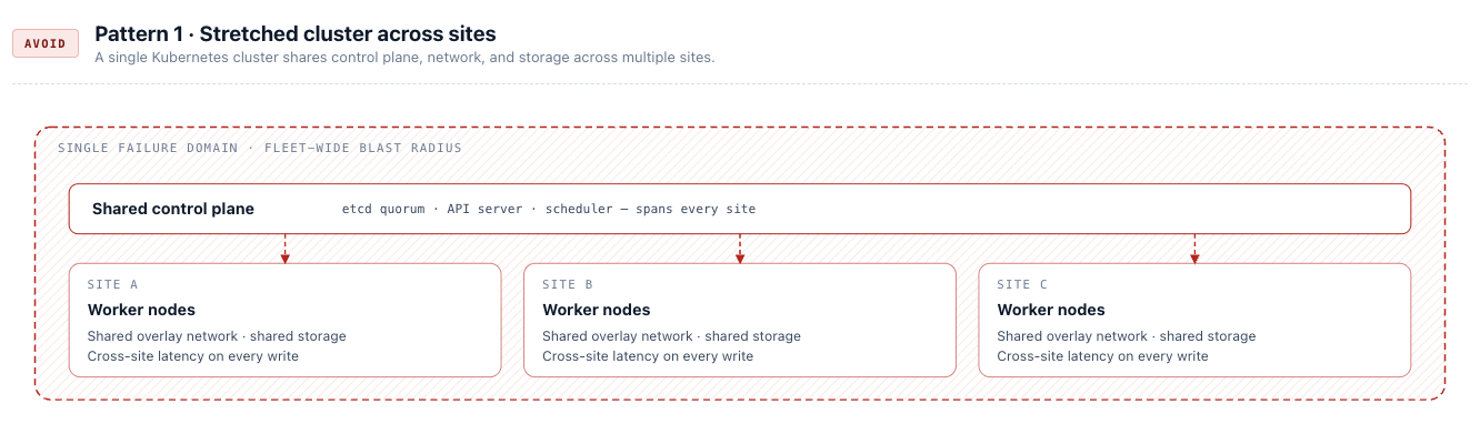
A stretched cluster treats a single Kubernetes cluster as a logical system spanning multiple physical sites. etcd is distributed across locations, layer 2 networking is extended between data centres, storage is synchronously replicated, and external load balancers redirect traffic between sites without changing application endpoints. The appeal is transparency — applications do not need to change, and failover appears automatic.
In practice, this model is extraordinarily brittle:
- etcd is highly sensitive to inter-site latency and packet loss. Maintaining a stable stretched control plane requires a guaranteed round-trip time (RTT) of less than 10 ms between sites — a constraint that limits viable stretched deployments to metro-distance private networks with dedicated low-latency links. Any network disruption between sites can destabilise the entire control plane even when application workloads are healthy.
- Timeouts must be increased to tolerate transient network issues — but those same extended timeouts directly delay failover when a real site failure occurs. There is no safe setting.
- The blast radius is enormous: a single misconfiguration, failed upgrade, or control plane instability affects all sites simultaneously. There is no independent execution path.
- Stretched layer 2 networking and synchronous storage replication are expensive to deploy and far more expensive to operate and troubleshoot. This model is generally only viable within metro distances on highly reliable private networks.
- Maintenance operations — upgrades, certificate rotation, network changes — must be coordinated across all sites simultaneously with no ability to isolate risk.
The complexity compounds over time and rarely simplifies. Teams that have operated stretched clusters consistently describe them as the most fragile component of their entire infrastructure. This pattern originates from the VMware HA/FT era, where infrastructure abstraction was the only tool available. Kubernetes does not improve these characteristics — it inherits them.
Do not design stretched Kubernetes clusters. The infrastructure complexity and operational fragility far outweigh the benefit of application transparency. This pattern is not recommended under any circumstances in this reference architecture.
Pattern 2: Independent Clusters — Strongly Recommended
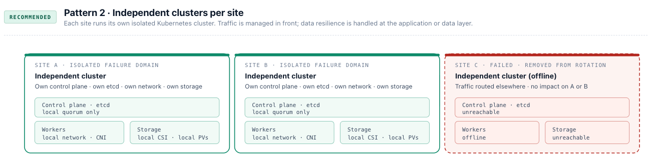
Each site or availability zone runs its own independent Kubernetes cluster with no shared control plane, networking, or storage. Clusters are isolated failure domains. A geo-distributed load balancer or DNS-based traffic manager sits in front of applications that support is, continuously health-checks each cluster endpoint, and routes traffic to healthy backends. If an entire cluster becomes unavailable, traffic is simply directed elsewhere. For applications that don’t support geo-distribution, or don’t need it, regular disaster recovery (see Chapter 11 — Data Protection ) covers fits the bill.
This is Kubernetes’ natural operational model, and its advantages compound at scale:
- Failures are contained. A control plane issue, storage problem, or misconfiguration affects one cluster only — not all sites.
- Each cluster can be operated, upgraded, and taken offline independently, enabling controlled maintenance with no fleet-wide risk.
- Blue/green deployments across clusters become a natural consequence of the architecture, not an additional pattern to engineer.
- Scaling to additional regions or sites is a repeatable pattern rather than an architectural redesign.
- At the extreme, a pool of single-node clusters (section 3.2.2, KubeSolo) can deliver higher overall availability than a single multi-node cluster, because the failure domain of each node is limited to that node alone.
The trade-off is explicit: applications must be designed to tolerate concurrent execution across sites, and data consistency is managed at the application or data layer — database replication, leader election, quorum-based writes, or eventual consistency depending on the workload. For legacy applications that cannot be adapted, this may require significant redesign.
This is not a trade-off to avoid — it is a design discipline. Applications explicitly resilient to failure scale reliably across regions and degrade gracefully under partial failure. Applications that depend on infrastructure to hide failure from them are only as reliable as that infrastructure, which is never reliable enough.
DR topology minimums by strategy. Active/passive DR — where a standby cluster takes over on primary failure — requires a minimum of two geographically separated clusters. Active/active DR — where both clusters serve live traffic simultaneously — requires a minimum of three clusters plus a witness mechanism using a consensus protocol to determine which instances are healthy and authoritative. Designing for active/active below this threshold produces split-brain risk rather than resilience.
All clusters in this reference architecture are independent, isolated failure domains. This is a non-negotiable architectural principle. External traffic management is addressed in Chapter 3, section 3.4 (Traffic Routing and Gateway API) and Chapter 2 for Portainer Server exposure. Stateful workload resilience and data layer DR patterns are covered in Chapter 11.
Scenarios and Maturity Levels
The scenarios for each chapter are based on Portainer's maturity levels. See the Appendix for more details about the maturity levels and a link to the assessment. Scenario build on each other and are relative to each other. Find the scenario closest to your current environment; implement relevant improvements from there.
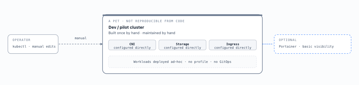
A single development or pilot cluster deployed manually without cluster profiles or central management. CNI, storage, and ingress are configured directly on the cluster. Portainer is optionally installed for basic visibility. The cluster is treated as a pet — manually maintained and not reproducible from code. Appropriate for learning, proof-of-concept, or the earliest stage of production adoption with no stateful or business-critical workloads.
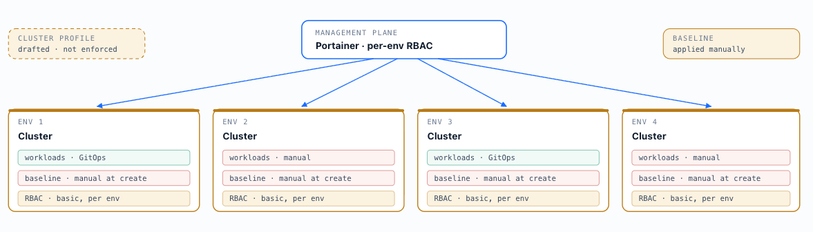
A handful of clusters registered as managed environments in Portainer. Basic RBAC is applied per environment. CNI, storage, and ingress are standardised through an agreed configuration but applied manually at cluster creation. Cluster profiles are being defined but not yet fully enforced. Some workloads use GitOps; others are deployed manually. Not all teams have embraced the same operational model via Portainer. Environments are beginning to be treated as cattle but still require individual attention during creation and maintenance.
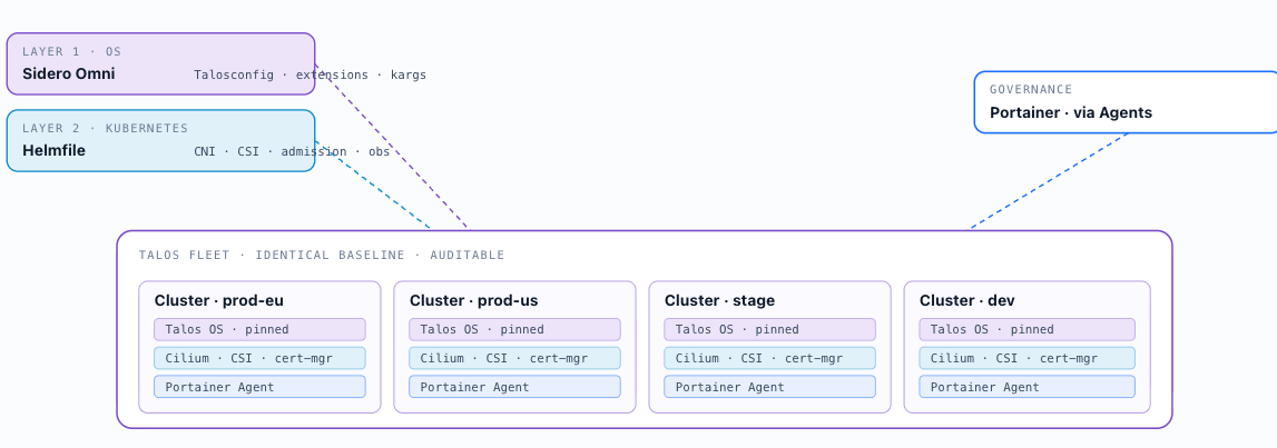
This scenario covers an organisation running a fleet of on-premises clusters built on Talos OS and upstream Kubernetes. Clusters are bootstrapped via the Talos API using talosctl , with Sidero Omni providing centralised lifecycle management — bootstrapping, upgrading, and scaling — as the fleet matures. This aligns with the upstream-aligned Kubernetes category (section 3.2). Cilium is the CNI of choice, providing native network policy enforcement and Gateway API support via its built-in controller.
Cluster profiles (section 3.6) are applied at bootstrap via a two-layer delivery model: Sidero Omni manages the node OS configuration layer — Talosconfig, Talos extensions, and kernel arguments — before any Kubernetes component is deployed; Helmfile then applies the Kubernetes component baseline — CNI, CSI, ingress, admission control, and observability agents — immediately after the API server is available. Both layers are required for a complete Talos cluster profile and are maintained independently of each other (section 3.7). This ensures every cluster in the fleet is provisioned to an identical, auditable baseline. Portainer manages the fleet through Agents installed into each cluster; no direct cluster API exposure is required from operator workstations.
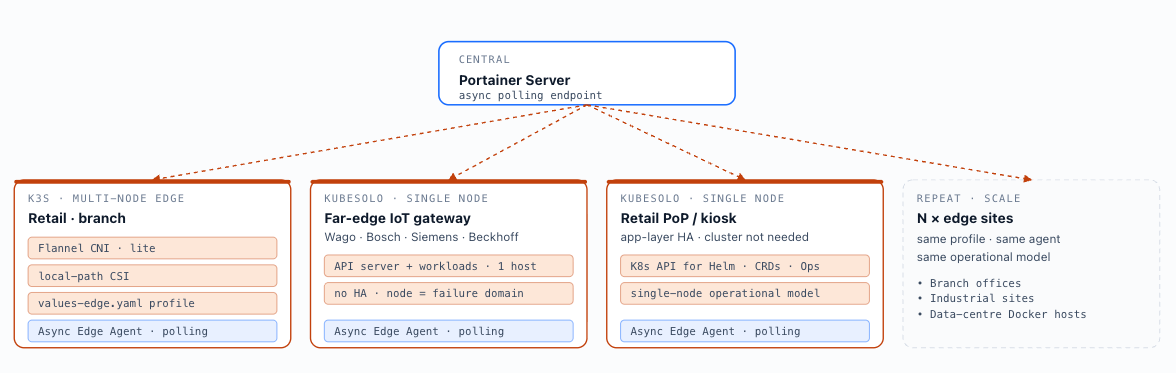
Edge deployments run K3s or KubeSolo on hardware with constrained resources — limited CPU, memory, and storage — and intermittent or high-latency connectivity to the central Portainer instance. The Async Edge Agent model (Chapter 2, section 2.3) is the required architecture: the agent operates in polling mode, fetching instructions from the Portainer Server at a configured interval and executing them locally without requiring a persistent connection. Local-path CSI storage replaces cloud or NFS storage; Flannel (for K3s) or a Cilium lite-mode CNI replaces full CNI stacks; the edge cluster profile includes a minimal admission control baseline sized for constrained node resources, delivered via Helmfile with a values-edge.yaml parameterisation (section 3.7). KubeSolo extends this pattern to single-node deployments, which run the full Kubernetes API server alongside workloads on a single host with no HA guarantees — appropriate for far-edge devices, retail point-of-presence, or industrial IoT gateways — such as the Wago CC100, Bosch Embedded Compute, Siemens SIMATIC IOT2000, and Beckhoff CX7000 — where node redundancy is physically unavailable and Kubernetes compatibility is mandated by industrial software platforms. The same architectural pattern applies to enterprise data centre Docker fleets: standalone servers running independently by design, where application-layer HA means no cluster is needed but the Kubernetes API is required to consume modern software. KubeSolo enables these environments to adopt Kubernetes-native tooling — Helm charts, CRDs, Operators — without transforming the single-node operational model that makes them stable and predictable.
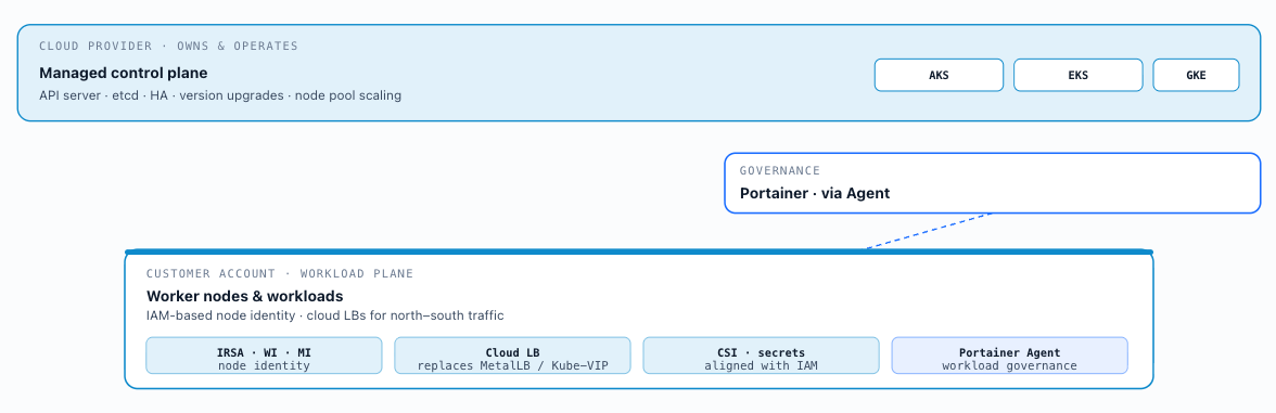
Cloud-managed Kubernetes hands the control-plane lifecycle to the cloud provider, reducing the operational burden of version upgrades, etcd management, and control-plane HA. For Portainer integration, cloud-managed clusters behave identically to self-managed once the Agent is installed. The principal architectural considerations are: IAM-based node identity (IRSA for EKS, Workload Identity for GKE, Managed Identity for AKS) must align with the CSI driver and secrets operator identity requirements described in Chapter 8; cloud load balancers replace MetalLB or Kube-VIP for north–south traffic (section 3.4); and cluster lifecycle operations (version upgrades, node pool scaling) are handled through the cloud provider's control plane rather than through Portainer. Cluster profiles specify the approved configuration state post-provisioning; Day-1 baseline components (admission controllers, observability agents) are applied at bootstrap via Helmfile — or, where Crossplane is the provisioning layer, as a Crossplane Composition that unifies cluster creation and profile delivery into a single declarative operation (section 3.7). After bootstrap, Portainer governs ongoing workload deployment and operational changes.
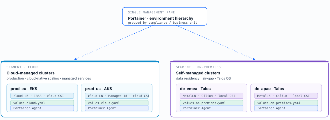
A hybrid fleet combines cloud-managed clusters for production workloads requiring cloud-native scaling and managed services with self-managed clusters for on-premises workloads subject to data residency or air-gap requirements. Portainer provides a single management pane across both segments via its environment hierarchy — cloud clusters and on-premises clusters are registered as separate environments within the same Portainer instance, grouped by compliance boundary or business unit. The primary operational challenge in hybrid fleets is configuration consistency: CNI, ingress, and storage abstractions differ between cloud and on-premises clusters, so cluster profiles must be authored in variants (cloud profile, on-premises profile) that encode the differences explicitly while enforcing common governance controls (admission policy, RBAC model, observability agents). Helmfile applies the appropriate profile variant to each cluster class at bootstrap — a shared helmfile.yaml parameterised by environment-specific values files ( values-cloud.yaml , values-on-premises.yaml ) — enforcing common governance controls while encoding the infrastructure differences explicitly. Where Crossplane is the provisioning layer for cloud clusters, profile components can instead be encoded as Crossplane Compositions for a unified provisioning and profile delivery model (section 3.7). Portainer then governs ongoing workload management across both cluster types through a single management surface.
Key Decisions Addressed
- Ch3-D-01 — Kubernetes Distribution: Use upstream-aligned Kubernetes as the default for all new deployments. On-premises production: Talos OS combined with upstream Kubernetes is the recommended default — immutable, API-driven, minimal attack surface. Edge and constrained: K3s or KubeSolo. Cloud: managed distributions (AKS, EKS, GKE). Other upstream-aligned distributions are supported where specific compliance requirements (FIPS certification, CIS benchmark obligations) or existing organisational investment require them. Vendor-augmented distributions (OpenShift, Tanzu) only where existing investment justifies the licence and operational overhead. — see section 3.2
- Ch3-D-02 — Node Operating System: Talos OS is the preferred operating system for new production cluster nodes — immutable, API-driven, no SSH access, and minimal attack surface. Enterprise Linux is acceptable where operational tooling ecosystems or existing organisational standards require it. All node OS images must be produced as golden images, versioned, and maintained centrally. — see section 3.2
- Ch3-D-03 — CNI Selection: Cilium is the recommended CNI for all new deployments. Calico is the validated alternative where Cilium's kernel requirements (Linux 5.10+) cannot be met. Flannel and Canal are not permitted in multi-tenant environments. Network policy enforcement is a hard requirement for the namespace isolation model; CNI selection must support it. — see section 3.3
- Ch3-D-04 — Traffic Routing Model: Gateway API is the required model for all new cluster deployments. Legacy ingress controllers are acceptable only for environments with existing investment — version-pinned within the cluster profile, with a documented migration timeline to Gateway API. — see section 3.4
- Ch3-D-05 — Storage Tiers and CSI: All clusters must define storage classes for each applicable tier (block, shared file, local-path) using the reference naming convention, with performance characteristics documented in the cluster profile. Block storage must support CSI snapshots and dynamic expansion. NFS-backed storage must not be used for databases or high-throughput stateful workloads, and must not be used for the Portainer database volume. For most enterprise scenarios, distributed or shared storage that tolerates node failure is required — local storage is not sufficient where workload continuity across node loss is expected. Solutions such as Portworx, rook-ceph, LINBIT SDS, or cloud-native distributed block storage provide the necessary resilience; storage tier selection must reflect the HA requirements of the workloads and the cluster’s failure domain. — see section 3.5
- Ch3-D-06 — Cluster Profiles: All clusters must be built from a version-controlled cluster profile maintained by the platform team. Ad-hoc cluster configuration is not permitted. Profile deviations must be tracked as exceptions, reviewed, and remediated. Clusters that cannot be assigned to a defined profile must not be onboarded to Portainer governance. — see section 3.6
- Ch3-D-07 — Cluster Provisioning Tooling: Portainer is the management and governance function — it does not provision clusters. Cluster provisioning is handled by dedicated tooling independent of Portainer: Crossplane for cloud and IaaS-based environments; Sidero Omni for Talos bare-metal (non-production only until identified capability gaps are addressed). These layers are independent and do not substitute for each other. — see section 3.7
- Ch3-D-08 — Existing Cluster Onboarding: All clusters onboarded to Portainer must be assigned to a cluster profile at onboarding time. Ungoverned clusters under Portainer management are an anti-pattern and not permitted. The onboarding process must include an RBAC audit, secrets audit, and network exposure review before governance controls are applied. — see section 3.8
- Ch3-D-09 — Profile Orchestration Tooling: Cluster profiles are implemented in the provisioning tooling layer — Portainer does not define, store, or apply them. All profile artefacts — Helmfile releases, Crossplane Compositions, Talosconfig templates, and Omni machine class definitions — must be version-controlled in a dedicated platform configuration repository. — see section 3.7
- Ch3-D-10 — Control Plane HA Topology: Production clusters must have a minimum of three control plane nodes to maintain etcd quorum through a single node failure. The API server endpoint must be fronted by a load balancer or virtual IP — Kube-VIP for on-premises Talos deployments — to allow node rotation without endpoint address changes. Stacked etcd is the default; external etcd is required only where the etcd failure domain must be provably independent of the API server. The HA topology must be defined in the cluster profile and encoded in the Talosconfig or Omni machine class definition before provisioning begins. — see section 3.2.3
- Ch3-D-11 — CIDR and Subnet Planning: Pod CIDR, Service CIDR, and node subnets are immutable cluster-creation-time decisions. All CIDRs must be unique and non-overlapping across the fleet, particularly where Cilium Cluster Mesh or cross-cluster routing is in use. CIDR selection is outside the scope of this reference architecture but must be documented in the cluster profile for each cluster type before provisioning begins. — see section 3.3
- Ch3-D-12 — Cluster Upgrade Strategy: All cluster component upgrades — OS, Kubernetes distribution, CNI, CSI, ingress controller, admission control — are expressed as profile version increments and applied via the same provisioning tooling used at cluster creation. Upgrades are validated in non-production before promotion to production. Kubernetes minor version rollback is not supported; all upgrades require pre-validated staging results. Portainer is not in the change path for cluster component upgrades. — see section 3.7
- Ch3-D-13 — cert-manager Is a Mandatory Baseline Component: cert-manager must be included in every cluster profile and deployed as part of the Day-1 baseline on every cluster. No cluster enters production without automated TLS certificate lifecycle management. Manual certificate management does not scale and creates renewal failure risk that is operationally unacceptable. cert-manager, ExternalDNS, and the Gateway API controller are co-dependent baseline components and must be deployed together at Day-1. — see section 3.5
- Ch3-D-14 — DNS-01 Challenge Solver Required for Production Certificates: DNS-01 challenge solvers are required for all production ACME certificate issuers. HTTP-01 is limited to publicly reachable clusters and does not support wildcard certificates. DNS-01 works with private, internal, and air-gapped-adjacent clusters and is required for wildcard certificate issuance. HTTP-01 is acceptable only for public non-production environments where the cluster is directly reachable from the public internet. — see section 3.5
- Ch3-D-15 — Internal CA Issuer for Air-Gapped and Regulated Environments: Environments where public CA certificates are inappropriate must use cert-manager with an internal CA issuer — Vault or OpenBao PKI engine (Chapter 8). This is the reference pattern for air-gapped clusters, regulated environments with certificate authority requirements, and any deployment where public ACME CAs are not reachable or not permitted. cert-manager authenticates to the PKI engine using the Kubernetes auth method. — see sections 3.5 and 8.2
- Ch3-D-16 — ExternalDNS Ownership ID Must Be Unique Per Cluster: Every ExternalDNS instance must be configured with a unique --txt-owner-id value per cluster. Without this, multiple ExternalDNS instances sharing the same DNS zone will treat each other’s records as unowned and may delete or overwrite them. Uniqueness must be enforced in the cluster profile definition. — see section 3.5
[1] Portainer, "The True Cost of Kubernetes Platform Adoption" . Managed Kubernetes labor reduction estimates (15–30%, varying by tier) referenced from Datadog, "State of Kubernetes," 2023 .